Common Facade Insulation Mistakes: A Technical Editorial on Enclosure Performance
The building envelope is common facade insulation mistakes often characterized as a shield, but in the rigorous reality of building science, it functions more like a metabolic filter. Insulation is the primary component of this filter, yet its efficacy is rarely a binary state of “present” or “absent.” Instead, the performance of a facade exists on a spectrum of thermal continuity and moisture management. As we move into an era of stringent energy mandates and heightened awareness of embodied carbon, the margin for error in insulation strategy has effectively vanished. A single discontinuity—a neglected thermal bridge or a misplaced vapor retarder—can negate the benefits of an otherwise high-performance assembly.
The complexity of modern building skins, which often involve layers of glazing, metal rainscreens, and complex stone geometries, has introduced a new generation of vulnerabilities. We are no longer dealing with simple mass-wall construction where thickness was the primary variable. Today, insulation must interact with air barriers, water-resistive membranes, and structural fasteners in a highly calibrated dance. When this orchestration fails, the consequences extend beyond mere energy loss; they manifest as interstitial condensation, structural rot, and catastrophic loss of indoor air quality.
This editorial reference moves beyond the surface-level symptoms of poor insulation. It deconstructs the systemic failures inherent in contemporary enclosure design, offering a forensic look at how technical misunderstandings at the planning stage translate into long-term liabilities. By examining these dynamics through the lens of common facade insulation mistakes thermodynamics and hygrothermal behavior, we provide a framework for achieving true enclosure integrity.
Understanding “common facade insulation mistakes”
To navigate common facade insulation mistakes, one must first discard the notion that R-value is a static property of a material. To a building scientist, an R-value is only as reliable as the assembly’s airtightness and the absence of thermal bypasses. A common misunderstanding in the industry is the “Center-of-Cavity” bias, where stakeholders assume that the performance of a wall is equivalent to the R-value printed on the insulation batting. In reality, the “Effective R-value”—which accounts for structural studs, fasteners, and floor slabs—is often 40% to 60% lower than the rated value.
Another layer of complexity involves the “Hygrothermal Paradox.” In the rush to insulate buildings more heavily, we often decrease the “drying potential” of the wall. When a facade is ultra-insulated, the exterior cladding remains colder in winter because less interior heat is escaping to warm it. This increases the risk that any moisture entering the assembly (either from interior vapor or exterior leaks) will stay trapped and condense on the first cold surface it hits. Overlooking this balance is among the most frequent errors in high-performance design, leading to what many call “the rot of the sealed box.”
Furthermore, oversimplification of the “Thermal Bridge” is a persistent issue. Designers often view metal masonry ties or aluminum window frames as minor penetrations. However, metal is a highly efficient thermal conductor; a single un-insulated steel lintel can act as a “thermal straw,” sucking heat out of a building and creating a localized cold spot on the interior wall. This cold spot then becomes a magnet for interior humidity, leading to “ghosting” or mold patterns that owners often misinterpret as roof leaks.
Deep Contextual Background: The Systemic Evolution
The evolution of building enclosures has transitioned from “Massive” to “Multi-component.” Historically, masonry mass walls provided a degree of “forgiveness.” If they got wet, they had enough storage capacity to hold the moisture until it could evaporate. Insulation was secondary because the thermal mass of the brick or stone smoothed out temperature fluctuations.
The mid-20th century shift to lightweight steel and wood framing changed the physics entirely. We began to fill the cavities with fiberglass or mineral wool, creating a “Barrier” approach. However, this introduced the problem of air infiltration. As we moved into the 21st century, the “Rainscreen” and “Continuous Insulation” (ci) models emerged to combat the inefficiencies of cavity insulation. The contemporary mistake is often one of “hybridization”—attempting to apply old mass-wall logic to new lightweight, high-performance systems without understanding the fundamental change in how heat and moisture move through the assembly.
Conceptual Frameworks and Mental Models
1. The “Pen Trace” Test
A fundamental framework for ensuring thermal continuity. One should be able to take a red pen and trace the line of insulation around the entire building section—including roofs, floors, and windows—without ever lifting the pen. Any gap in that line is a guaranteed failure point where energy will escape and condensation will likely form.
2. The “Drying Potential” Framework
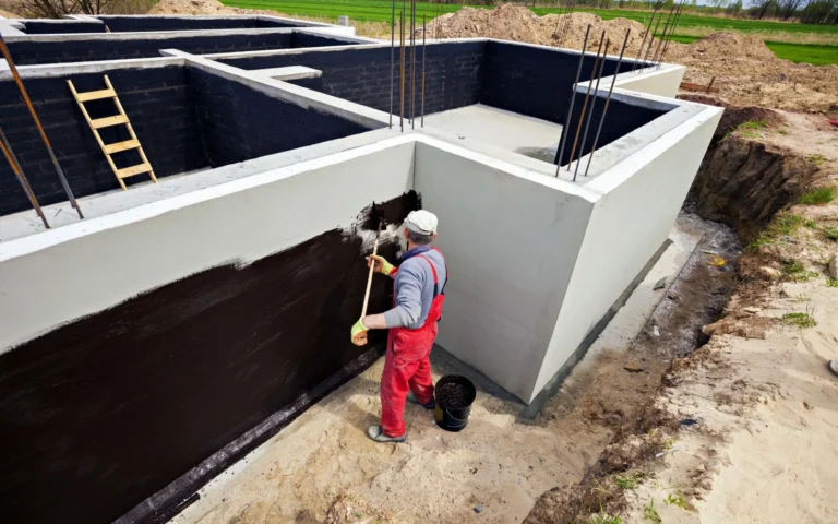
This model posits that every wall will eventually get wet, either through a sealant failure, a pipe leak, or vapor diffusion. The primary goal of insulation design is not just to keep the heat in, but to ensure that the wall can dry to at least one side (preferably both). Mistakes happen when vapor-closed insulation is placed on both the interior and exterior of a structure, creating a “vapor sandwich” that traps moisture.
3. The “Perfect Wall” Mental Model
Developed by building scientists like Joseph Lstiburek, this model places the control layers (water, air, vapor, and thermal) on the outside of the structural members. This keeps the “bones” of the building at a constant interior temperature and protects them from the elements. Deviating from this model by putting insulation only inside the studs is the root of most thermal bridging errors.
Key Categories: Material and Systemic Variations
When identifying common facade insulation mistakes, it is useful to categorize them by how they manifest across different systems.
| Category | Primary Error | Technical Consequence | Long-Term Impact |
| Cavity Insulation | Compressing batts | Reduced R-value; air pockets | Convective loops; cold spots |
| Continuous (ci) | Un-insulated fasteners | Thermal bridging | Reduced effective R-value by 15%+ |
| Spray Foam | Improper mixing/depth | Delamination; off-gassing | Air leakage; shrinkage gaps |
| Mineral Wool | Clogging drainage plane | Trapped moisture | Saturated insulation; mold |
| EIFS Systems | Missing “kick-out” flashing | Water entry behind foam | Substrate rot; systemic collapse |
| Vapor Retarders | Misplacement (Wrong side) | Interstitial condensation | Hidden mold; structural decay |
Decision Logic: The “Climate-Specific” Filter
In a cooling-dominated climate (Miami), the error is often placing the vapor barrier on the interior, which traps humidity pushed inward by the AC. In a heating-dominated climate (Minneapolis), the mistake is the reverse. The “best” insulation is the one that respects the dominant vapor drive of its specific geography.
Detailed Real-World Scenarios and Secondary Effects
Scenario 1: The “Ghosting” of the Steel Stud
A new commercial mid-rise in a cold climate utilized high-R-value fiberglass batts between steel studs but omitted exterior continuous insulation.
-
The Error: The steel studs acted as thermal bridges, staying significantly colder than the insulated cavity.
-
The Effect: Interior humidity condensed on the drywall directly over each stud. Over time, dust adhered to these damp spots, creating vertical gray stripes (“ghosting”) throughout the interior.
-
Failure Mode: Aesthetic rejection by the tenant and localized mold growth.
Scenario 2: The “Balcony Slab” Heat Sink
A luxury residential tower featured beautiful cantilevered concrete balconies.
-
The Error: The concrete slab was poured as a single continuous piece from the interior floor to the exterior balcony with no thermal break.
-
The Effect: The balcony acted as a giant radiator fin, pumping heat out of the apartments.
-
Secondary Effect: The interior floor near the glass stayed so cold that residents complained of “freezing feet,” and ice formed on the baseboards during extreme cold snaps.
Scenario 3: The “Closed-Cell” Vapor Trap
A retrofit project applied closed-cell spray foam to the interior of a historic brick wall.
-
The Error: The foam prevented the brick from drying toward the interior.
-
The Effect: In winter, moisture in the brick froze because it no longer received heat from the building.
-
Failure Mode: The face of the historic brick began to “spall” or pop off as the ice expanded, destroying the facade’s integrity.
Planning, Cost, and Resource Dynamics
The economics of facade insulation are often misunderstood through the lens of “First Cost” versus “Lifecycle Cost.”
| Strategy | CAPEX Premium | Energy Savings (Typical) | ROI Period |
| Code-Minimum (Studs) | 0% | Baseline | N/A |
| Continuous Ext. Insulation | 10–15% | 20–30% | 4–7 Years |
| Aero-gel / High-Tech | 50%+ | 35–45% | 15–20 Years |
| Thermal Break Hardware | 2–5% | 5–10% | 3–5 Years |
Opportunity Cost: The greatest cost is often “Right-Sizing.” By spending $50,000 more on exterior continuous insulation and thermal breaks, a developer can often save $100,000 on a smaller, less complex HVAC system. Failing to coordinate these disciplines is a pervasive planning mistake.
Tools, Strategies, and Support Systems
-
Thermal Imaging (Infrared): The gold standard for identifying gaps in insulation and thermal bridges after installation.
-
THERM Modeling: Software used to calculate the specific heat flow through complex junctions (like a window-to-wall transition).
-
WUFI Analysis: Modeling the hygrothermal (heat and moisture) movement through a wall over a 10-year period.
-
Blower Door Testing: Essential for verifying that the insulation isn’t being bypassed by air leakage.
-
Thermal Break Fasteners: Non-conductive (often fiberglass or specialized plastic) clips that hold cladding while minimizing heat transfer.
-
Low-Conductivity Lintels: Using stainless steel or coated members that have lower thermal conductivity than standard carbon steel.
Risk Landscape: A Taxonomy of Compounding Failures
-
The “Thermal Bypass” Risk: When air moves around or through insulation (convective loops), rendering the R-value irrelevant.
-
The “Concealed Condensation” Risk: This is the most dangerous failure, as it happens inside the wall where it cannot be seen until structural failure occurs.
-
Material Incompatibility: Using a petroleum-based spray foam that reacts with a specific rubberized flashing, leading to a breakdown of the water-resistive barrier.
-
Sequence Risk: Installing insulation when the substrate is damp, trapping moisture that will later lead to mold.
Governance, Maintenance, and Long-Term Adaptation
Insulation is not a “fit and forget” component. Its performance is tied to the governance of the building enclosure.
The Stewardship Checklist
-
Pre-Cladding Inspection: A mandatory “Red Pen” walk-through to ensure every thermal break is installed before the facade is closed.
-
5-Year Infrared Audit: Specifically looking for settled insulation (common in blown-in products) or compromised seals.
-
Ventilation Monitoring: If the facade is “tightened” through better insulation, the HVAC’s mechanical ventilation must be audited to ensure CO2 and humidity levels are managed.
-
Adaptation Triggers: If local climate data shows a shift toward higher humidity or more extreme heat, the “vapor drive” of the assembly should be re-evaluated during any major renovation.
Measurement, Tracking, and Evaluation
-
Leading Indicators: THERM model results during design; fastener-count-to-insulation-area ratios.
-
Lagging Indicators: Utility bill data; interior surface temperature readings during peak winter/summer.
-
Qualitative Signals: Occupant comfort surveys. If people in a “green” building are using space heaters, the insulation strategy has a fundamental flaw.
-
Documentation Example: A “Thermal Integrity Map” provided to the owner at handover, detailing the location of all thermal breaks and insulation types.
Common Misconceptions and Oversimplifications
-
Myth: “More insulation is always better.”
-
Correction: Excessive insulation without a drying strategy creates moisture traps.
-
-
Myth: “Air gaps are good insulators.”
-
Correction: Un-ventilated air gaps larger than 3/4 inch often develop “convective loops” that actually move heat across the cavity.
-
-
Myth: “Spray foam is a magic bullet for air sealing.”
-
Correction: It can pull away from studs as it cures or as the building settles, creating hidden air leaks.
-
-
Myth: “Standard masonry ties don’t affect R-value much.”
-
Correction: Hundreds of metal ties can degrade a wall’s performance by as much as 25%.
-
-
Myth: “Vapor barriers should be waterproof.”
-
Correction: They are two different functions; a vapor retarder limits molecular movement, while a WRB stops liquid water.
-
-
Myth: “You can insulate a historic building the same as a new one.”
-
Correction: Historic mass walls need to lose some heat to stay dry; over-insulating them can lead to structural decay.
-
Conclusion: The Ethics of Enclosure
The avoidance of common facade insulation mistakes is ultimately an act of architectural honesty. It requires moving beyond the “aesthetic skin” to respect the thermodynamic laws that govern our environment. A building that is beautifully clad but poorly insulated is a failure of stewardship—it wastes energy, compromises health, and burdens future generations with the cost of remediation.
As we move toward a “fabric-first” approach in 2026, the facade must be treated as a unified high-performance system. The mastery of insulation is found in the details: the thermal break at the balcony, the continuity of the air barrier, and the calculated drying potential of the assembly. When these elements are aligned, the building becomes more than just a shelter; it becomes a resilient, efficient, and healthy participant in the urban ecosystem.