Top Perforated Metal Panel Plans: A Definitive Guide to Architectural Perforation
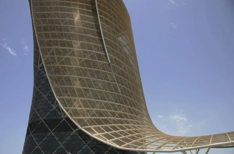
The architectural envelope has long struggled with the tension between the need for enclosure and the desire for porosity. Perforated metal panels represent the technological resolution of this conflict, acting as a “smart” skin that modulates environmental flux without the weight or opacity of traditional masonry. When we discuss the engineering behind the most successful installations, we are looking at a sophisticated interplay of material chemistry and geometric precision.
As building performance requirements become more stringent under 2026 energy codes, the role of perforated metal has expanded into the realm of passive climate control. By varying the “open area” of a panel, designers can create a gradient of thermal resistance that responds to the specific sun-path of a building’s orientation. This is a departure from the “uniform skin” approach of the 20th century.
However, the implementation of such systems is fraught with technical complexity. A perforated panel is essentially a weakened plate. The act of removing material to create an aesthetic or functional pattern fundamentally alters the structural behavior of the metal, introducing new variables in wind-load resistance, vibration, and galvanic corrosion. To manage these projects effectively, one must look beyond the pattern and into the physics of the assembly. This guide provides a rigorous framework for navigating these variables, serving as a definitive reference for those seeking to implement high-level enclosure strategies.
Understanding “top perforated metal panel plans”
To grasp the depth of top perforated metal panel plans, one must move past the misconception that perforation is a purely subtractive process. In the world of high-performance facades, perforation is an additive strategy for functionality. A “plan” in this context is not just a CAD drawing of holes; it is a comprehensive technical roadmap that reconciles the “Open Area Ratio” with the “Span-to-Thickness Ratio.” In reality, the “Staggered Pitch” and the “Bar Width”—the solid metal remaining between holes—dictate whether a panel will remain flat or “oil-can” under thermal stress.
Multi-perspective analysis reveals that a successful plan must address the “Moire Effect” and visual “Aliasing.” Managing this requires a deep understanding of optical interference. Furthermore, from a structural perspective, the “Plan” must account for the “Edge Margin.” Panels that are perforated to the very edge lose their ability to be mechanically fastened without tearing; therefore, a sophisticated plan incorporates “Solid Borders” that act as the structural frame for the perforated field.
Oversimplification risks are highest when discussing “Open Area.” Designers often request a 50% open area to maximize transparency, but fail to realize that this reduces the structural stiffness of the panel by more than 50%. This necessitates thicker gauges or more frequent sub-girts, which can exponentially increase the project’s carbon footprint and budget.
Deep Contextual Background: The Evolution of Industrial Porosity
The history of perforated metal is rooted in the industrial revolution’s need for filtration and separation. In the 19th century, perforated sheets were used primarily for mining and agriculture—sorting grain or coal. These were utilitarian components, punched by massive mechanical presses with little regard for aesthetics.
The mid-20th century saw the transition of perforation from the factory floor to the building facade. The advent of the “International Style” and the rise of the curtain wall created a demand for sun-shading devices. Architects like Le Corbusier began experimenting with “Brise Soleil,” but it was the development of CNC (Computer Numerical Control) punching and laser-cutting technology in the late 20th century that truly liberated the material.
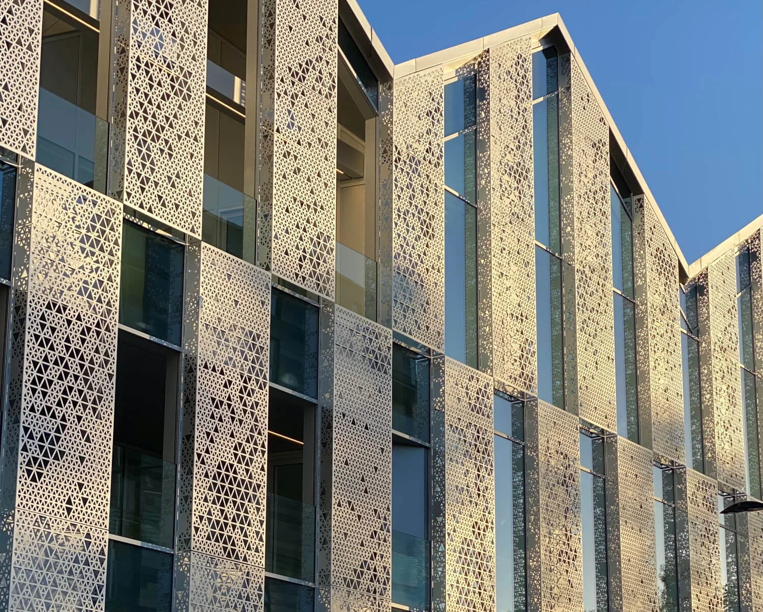
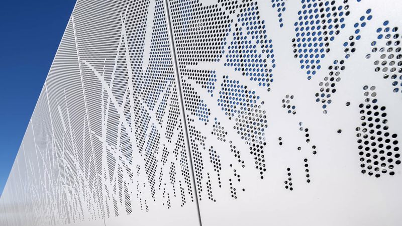
Today, we are in the era of “Parametric Perforation.” We can now translate complex photographic images or environmental data sets into millions of unique holes. This has turned the building envelope into a digital canvas. However, this aesthetic freedom has outpaced the general understanding of the material’s physical limits.
Conceptual Frameworks and Mental Models
1. The “Structural Diaphragm” Framework
This model treats the perforated panel not as a screen, but as a structural plate with “Virtual Thickness.” When material is removed, the effective thickness of the panel for calculation purposes is reduced. This framework allows engineers to determine the “Equivalent Solid Thickness,” which is critical for calculating how much the panel will deflect under a 100-mph wind load.
2. The “Filter Logic” Model
This mental model views the facade as a filter for four distinct inputs: Light, Air, Sound, and Sight. A successful plan balances these. For example, a “Visual Privacy” plan might use a small hole with a wide pitch to block views from the street, while an “Acoustic Plan” might use a high open-area ratio with a fibrous backing to absorb sound energy.
3. The “Boundary Layer” Thermal Model
This model looks at the air gap behind the perforated panel. The panel acts as a “pressure equalizer.” In hot climates, the air between the panel and the building heats up and rises (the stack effect), drawing cooler air in through the bottom perforations. This framework treats the cladding as a passive cooling machine, rather than just a shield.
Key Categories: Variations and Trade-offs
Selecting a system requires a negotiation between the “Visual Grain” and the “Mechanical Integrity.”
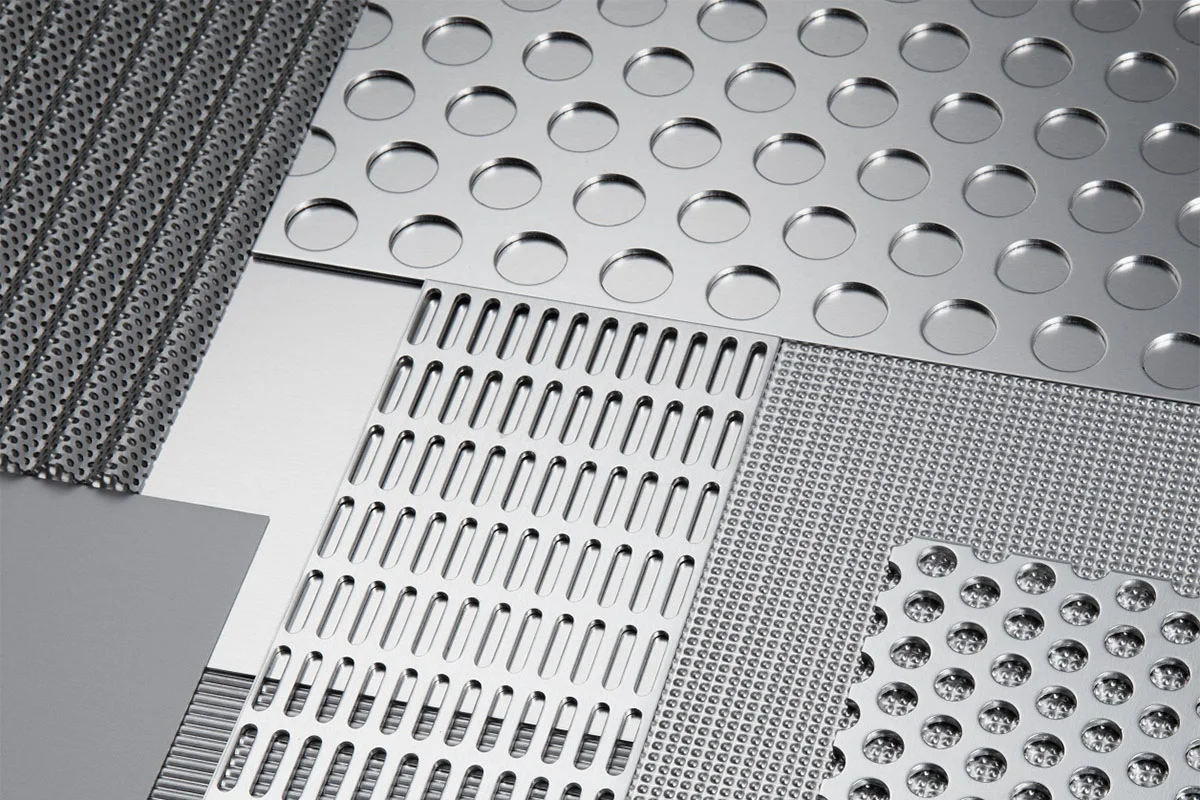
| Pattern Category | Primary Logic | Trade-off | Ideal Application |
| Standard Round | 60-degree staggered pitch | Highest strength-to-weight | Industrial / HVAC |
| Square Hole | Maximum open area | Prone to corner cracking | High-flow ventilation |
| Slotted / Oblong | Directional transparency | Weak in the “short” axis | Solar shading |
| Hexagonal | “Honeycomb” aesthetics | Complex to manufacture | High-end architectural |
| Parametric / Image | Variable hole sizes | Highest cost; complex CAD | Landmark facades |
| Micro-Perforation | Holes < 1mm | Looks solid from distance | Acoustic absorption |
Realistic Decision Logic: The “Pitch” Filter
If the goal is “Visual Smoothness,” the pitch (distance between holes) must be small enough that the human eye cannot resolve the individual circles at the typical viewing distance. If the pitch is too large, the building looks “dotted” rather than “transparent.” However, a tighter pitch increases the number of “hits” the punching machine must make, which can warp the metal due to the accumulation of internal stresses.
Detailed Real-World Scenarios and Implementation
Scenario 1: The “Aeolian Whistle” in Urban Canyons
A high-rise in a windy city utilized square-hole perforated panels for a parking garage screen.
-
The Failure: At certain wind speeds, the sharp edges of the square holes created “Vortex Shedding,” resulting in a loud whistling sound that disturbed neighbors.
-
The Fix: Replacing the panels with round-hole patterns and varying the hole sizes to “break” the harmonic frequency.
-
The Lesson: Top perforated metal panel plans must include an acoustic wind-tunnel simulation in high-velocity zones.
Scenario 2: The “Galvanic Bridge” in Coastal Zones
An oceanfront library used aluminum perforated panels with stainless steel fasteners.
-
The Failure: The salt spray stayed trapped in the “crevices” of the perforations. Despite both metals being durable, the “area ratio” was wrong. The large aluminum panel acted as an anode and began to corrode rapidly around the small stainless screws.
-
The Fix: Utilizing nylon isolators and a “Teflon-coated” fastener system.
Scenario 3: The “Oil-Canning” of Large Format Panels
A museum used 5’x12′ perforated sheets with a high open area (40%).
-
The Failure: Because the panels lacked a solid “Edge Margin,” they had no stiffness. Under summer heat, the metal expanded and the panels “buckled” or “oil-canned,” creating an unsightly wavy appearance.
-
The Fix: Adding “Stiffener Ribs” to the back of the panels and reducing the panel size to 4’x8′.
Planning, Cost, and Resource Dynamics
The economics of perforation are counter-intuitive: you are paying more for the material that has been removed. The cost is driven by “Machine Time” and “Tooling Wear.”
Cost and Variability Table (2026 Projections)
| Plan Complexity | Cost ($/sq ft) | Lead Time | Resource Intensity |
| Stock Patterns | $12 – $22 | 2-4 Weeks | Low (Standard tools) |
| Custom Scale | $25 – $45 | 6-10 Weeks | Moderate (Setup time) |
| Parametric / Art | $60 – $120+ | 12-20 Weeks | High (Laser/Waterjet) |
| Pre-Patinated | +$15 | +2 Weeks | High (Chemical) |
Opportunity Cost: Choosing a cheaper, thinner gauge to save $5/sq ft often leads to an “Attachment Debt.” Thinner panels require twice as many support brackets to prevent vibrating in the wind, which ultimately costs $15/sq ft more in labor and hardware.
Tools, Strategies, and Technical Support Systems
-
Parametric Design (Grasshopper/Rhino): Essential for generating “Gradient Patterns” that respond to solar data.
-
Structural Finite Element Analysis (FEA): Modeling the stress concentrations around the holes to ensure the panel doesn’t “tear” under peak wind loads.
-
Acoustic Simulation (CATT-Acoustic): Predicting the NRC (Noise Reduction Coefficient) of the assembly.
-
Leveling / Tensioning: High-quality plans require the panels to go through a “Leveling Line” after perforation to remove the “internal coil set” and ensure flatness.
-
Coating Integrity (Kynar 500): Perforated panels must be “Post-Painted.” If you perforate pre-painted metal, the edges of the holes are raw and will rust immediately.
-
Edge Margin Control: Defining “Non-Perforated Zones” for folding and bolting.
-
Bird/Insect Screening: Integrating a fine mesh behind large-hole perforations to prevent nesting in the wall cavity.
-
Automated Punching Lines: Utilizing multi-turret presses for speed and consistency.
Risk Landscape: A Taxonomy of Perforation Failure Modes
-
Thermal “Creep”: In long runs of perforated metal, the sum of the expansion can shear the end fasteners.
-
Resonance Frequency: If the “vibration frequency” of the panel matches the wind gusts, the panel can rattle itself apart.
-
“Shadow Leaks”: When the perforation pattern allows sun to hit the “Waterproof Membrane” behind it, UV degradation can destroy the building’s actual waterproofing in 5 years.
-
Corrosion “Bleeding”: On steel panels, rust from the raw edges of the holes “runs” down the face, staining the building.
Governance, Maintenance, and Long-Term Adaptation
A perforated facade is a “High-Surface-Area” asset. It collects more dust, salt, and soot than a solid wall.
The Stewardship Checklist
-
Annual “Salt Flush”: For coastal projects, a low-pressure water wash is mandatory to remove salts from the interior edges of the perforations.
-
Fastener Torque Check: Perforated panels vibrate; bolts can loosen over 10 years.
-
Drainage Audit: Ensure the “J-Channels” at the bottom of the panels are not clogged with debris that fell through the holes.
-
Pattern Integrity: Checking for “Bar Cracking”—small fissures between holes that indicate the panel is over-stressed.
Measurement, Tracking, and Evaluation
-
Leading Indicator: “Flatness Deviation” (measured in millimeters per meter) before installation.
-
Lagging Indicator: “Light Transmission” levels in the interior (to see if the shading goals were met).
-
Qualitative Signal: The absence of “vibration hum” during the first major storm.
-
Quantitative Signal: Measuring the temperature of the “Air Gap” behind the panel vs. the exterior temperature to verify the cooling effect.
Common Misconceptions and Oversimplifications
-
Myth: “Laser cutting is always better than punching.”
-
Correction: Laser cutting creates “Heat Affected Zones” that can make the metal brittle. Punching is often structurally superior for large runs.
-
-
Myth: “You can use any image for a parametric facade.”
-
Correction: High-contrast images with too much detail require holes so small and close together that the panel loses all structural integrity.
-
-
Myth: “Perforated metal is a good security fence.”
-
Correction: High-open-area panels can act as a “ladder” for intruders if the hole size allows for toe-holds.
-
-
Myth: “Perforation reduces the weight of the building.”
-
Correction: While the panel is lighter, the system is often heavier because you must use a thicker gauge to regain the lost stiffness.
-
-
Myth: “Holes don’t need to be deburred.”
-
Correction: Sharp burrs on the back of the holes trap moisture and accelerate corrosion.
-
-
Myth: “All metals perforate the same.”
-
Correction: Stainless steel “Work-Hardens” during punching, making it much harder on tools than aluminum or mild steel.
-
Ethical and Practical Considerations
In 2026, we must address the “Resource Intensity” of perforation. The “Scrap Rate” of a 40% open-area panel is significant. Ethical top perforated metal panel plans prioritize “Circular Manufacturing,” where the “slugs” (the circles of metal punched out) are immediately collected and sent back to the smelter. Furthermore, we must consider “Avian Safety.” Certain hole patterns and transparency levels can confuse birds, leading to strikes. A responsible plan incorporates “Visual Markers” or specific “Contrast Ratios” that make the facade visible to local bird populations while remaining transparent to humans.
Conclusion: The Precision of Porosity
The move toward more porous, responsive architecture is irreversible. As we seek to build enclosures that are more like skin and less like armor, the perforated metal panel remains our most versatile tool.
A definitive approach to top perforated metal panel plans requires a humble respect for the material’s limits. It is a discipline that rewards those who balance the “Aesthetic Dream” with the “Mechanical Reality.” When the pitch is correct, the gauge is sufficient, and the attachment logic is sound, a perforated facade does more than just shield a building—it allows the building to exist in harmony with its environment, breathing, cooling, and modulating light with the grace of a living organism.