How to Avoid Facade Cracking Risks: A Definitive Guide to Building Envelopes
In the hierarchy of building failures, few issues are as visually alarming or technically complex as the development of fractures in a building’s exterior. A crack in a facade is rarely an isolated event; it is the physical manifestation of an unresolved tension between the building’s rigid internal skeleton and the volatile external environment. As we push toward more ambitious architectural forms and thinner, higher-performance material assemblies, the forces acting upon the building envelope have intensified. To view a crack as a mere cosmetic blemish is to ignore the fundamental physics of structural movement, moisture ingress, and thermal dynamics.
Modern building envelopes are no longer the monolithic, load-bearing masonry walls of the previous century. When the design fails to account for these “differential movements,” the energy must find an outlet, and that outlet is almost invariably a structural or superficial fracture.
The stakes for managing these risks have escalated. A breached facade is a gateway for bulk water, which catalyzes secondary failure modes such as steel corrosion, mold growth, and the loss of thermal efficiency. In the professional landscape of 2026, where asset longevity and carbon retention are paramount, the ability to anticipate and mitigate these fractures is a core competency for architects, engineers, and facility managers alike. This article deconstructs the systemic causes of envelope failure to provide a definitive reference for maintaining the integrity of the built environment.
Understanding “how to avoid facade cracking risks.”
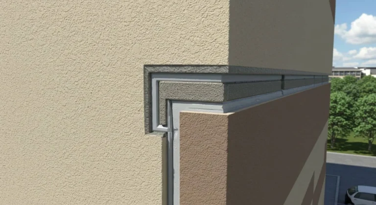
To truly grasp how to avoid facade cracking risks, one must move beyond the “patch and paint” mentality. In professional engineering, a crack is viewed as a symptom of a systemic “Movement Conflict.” This conflict typically arises when two materials with different coefficients of thermal expansion are rigidly attached. For example, when a metal trim is fixed to a brick substrate without a sliding joint, the metal will expand faster than the brick in the summer sun, exerting a shearing force that will eventually tear the masonry or buckle the metal.
A common misunderstanding is that “stronger” materials are the solution. In reality, the most resilient facades are often those designed with “Strategic Weakness”—that is, the inclusion of control joints and expansion gaps that allow the building to move without stressing the primary materials. Oversimplification in this field often leads to the misuse of sealants; many believe a high-strength epoxy can “glue” a crack shut permanently.
From a multi-perspective view, the architect sees cracking as an aesthetic failure; the structural engineer sees it as a load-transfer issue; and the building scientist sees it as a moisture-entry point. A comprehensive plan to avoid these risks must satisfy all three viewpoints.
Deep Contextual Background: The Evolution of Envelope Stress
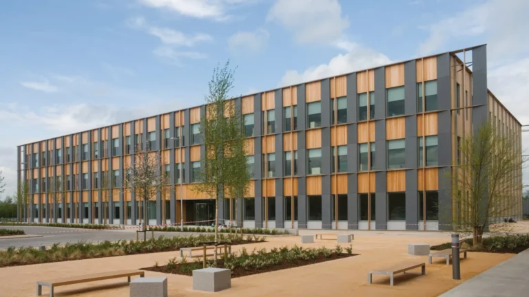
The thick masonry walls of the pre-industrial era acted as a massive thermal sink, absorbing heat slowly and distributing structural loads over a wide footprint. These buildings moved, but they did so with high “internal damping.” The shift to the “Curtain Wall” and “Rain-screen” systems in the mid-20th century fundamentally changed the risk profile. By separating the skin from the structure, we created a lightweight envelope that responds almost instantly to temperature changes.
In the 1970s and 80s, the introduction of Exterior Insulation and Finish Systems (EIFS) highlighted the dangers of thin-coat chemistry. These systems were prone to cracking at window corners because they lacked the “fracture toughness” to handle the concentration of stress at those points. Today, in 2026, we are dealing with “Hyper-Form Facades”—curved glass, ultra-high-performance concrete (UHPC), and large-format sintered stones. These materials have virtually zero tolerance for structural deflection. As we build taller and thinner, the “racking” forces from wind loads have become a primary driver of facade fractures, requiring more sophisticated decoupling strategies than ever before.
Conceptual Frameworks and Mental Models
1. The “Coefficient of Differential Movement.”
This framework requires calculating the expansion of every layer in a wall assembly. Failure to calculate this “Differential” is the leading cause of shear cracks in modern cladding.
2. The “Stress Concentration” Mental Model
In any rigid plane, stress will find the sharpest point to release. This is why cracks almost always originate at the 90-degree corners of window and door openings. A superior design uses “re-entrant corner reinforcement” or rounded geometries to dissipate these forces.
3. The “Elasticity vs. Brittleness” Spectrum
Materials exist on a spectrum. Concrete and stone are brittle; they have high compressive strength but fail instantly under tension. Metal and polymers are elastic. The mental model for avoiding risks is to use elastic materials (sealants and gaskets) at the “transition points” where the brittle materials meet.
Key Categories of Facade Fractures and Trade-offs
| Fracture Category | Primary Driver | Visual Signature | Typical Mitigation |
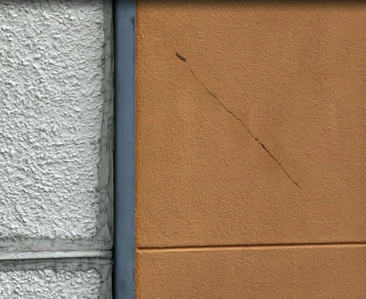
| Thermal Expansion | Solar Radiation | Vertical cracks at corners | Expansion joints every 20-30 feet |
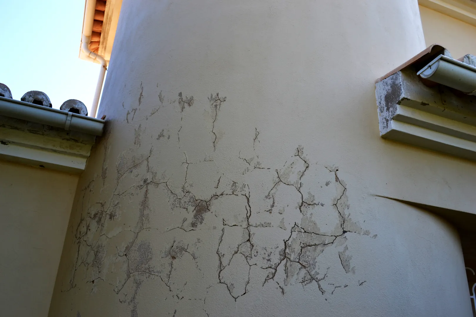
| Structural Settlement | Foundation shift | Diagonal “stair-step” cracks | Piling or soil stabilization |
| Hygroscopic Swell | Moisture Absorption | Bowing or “pillowing” panels | Back-side ventilation (Rainscreen) |
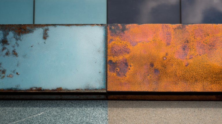
| Corrosion Jacking | Rusted Rebar/Wall Ties | Linear cracks along steel lines | Stainless steel components |
| Wind Racking | Lateral Force | Diagonal shear cracks | Flexible structural attachments |
| Creep | Long-term Load | Horizontal “bulging” | Compression joints in tall buildings |
Decision Logic: The “Rigidity Filter”
A “Closed” system (like traditional stucco) relies on the material’s own tensile strength to resist cracking. An “Open” system (like a terracotta rainscreen) acknowledges that movement will happen and provides gaps between every panel to accommodate it. In high-rise applications, “Open” systems are almost always superior for risk mitigation.
Detailed Real-World Scenarios and Decision Points
Scenario 1: The “South-Facing” High-Rise
A building in a high-altitude city experiences intense UV and a 60-degree temperature swing daily.
-
The Risk: Dark-colored metal panels buckle and pop their fasteners because they were “hard-pinned” to the studs.
-
The Solution: Utilizing “floating” clips that allow the panels to slide up and down without losing their attachment to the building.
Scenario 2: The “Coastal” Masonry Restoration
An old brick building is being retrofitted with new windows.
-
The Risk: New, rigid steel lintels are installed over the windows without a “bond breaker.”
-
Failure Mode: The different expansion rates of the steel and the old lime-mortar brick cause “spalling,” where the face of the brick literally pops off.
-
Decision Point: Use stainless steel lintels with a specialized flashing that allows the brick to slide independently of the steel.
Scenario 3: The “Soft-Story” Seismic Zone
A building in a seismic region is subject to frequent micro-vibrations.
-
The Risk: Rigid stone cladding shatters during a minor tremor because it was directly mortared to the backup wall.
-
The Solution: A unitized curtain wall system where each panel is “hung” on a pivot that can sway during an earthquake without transferring the stress to the stone.
Planning, Cost, and Resource Dynamics
The cost of adding an expansion joint during construction is negligible, whereas the cost of “pinning” a structural crack in a finished building involves scaffolding, engineering, and often, legal fees.
Range-Based Resource Allocation
| Intervention | Initial Cost Impact | Long-term ROI | Reliability |
| Standard Control Joints | < 1% of facade budget | 500% (Prevents redo) | High |
| Stainless Steel Ties | 2-3% of facade budget | High (Prevents rust-jacking) | Excellent |
| Thermally Broken Sub-frames | 5-8% of facade budget | High (Energy + Durability) | Excellent |
| Fiber-Reinforced Renders | 2-4% of facade budget | Moderate | Good |
Opportunity Cost: The hidden cost of facade cracking is “Brand Degradation.” For commercial real estate, visible cracks suggest structural instability to prospective tenants, leading to higher vacancies and lower lease rates.
Tools, Strategies, and Technical Support Systems
-
Finite Element Analysis (FEA): Software used to model stress points in a facade design before a single brick is laid.
-
Laser Scanning (LiDAR): Creating a “Digital Twin” to monitor if a building is leaning or settling in real-time.
-
Coefficient of Linear Thermal Expansion (CLTE) Testing: Laboratory testing of specific material batches to ensure they meet the design specs.
-
Slip-Clips and Z-Girts: Mechanical hardware that decouples the outer skin from the inner structure.
-
Bond Breakers: Simple tapes or liquids that prevent sealants from sticking to three sides of a joint, which is a leading cause of sealant tearing.
-
Ultrasonic Pulse Velocity (UPV): A non-destructive tool used to find internal cracks in concrete or stone before they reach the surface.
-
Hygrothermal Modeling (WUFI): Predicting how moisture-related swelling will impact the dimensional stability of wood or composite facades.
Risk Landscape and Failure Modes: A Taxonomy
Cracking rarely happens in a vacuum. It is often the first step in a “Failure Cascade.”
-
The “Moisture-Corrosion” Loop: A hairline crack allows water to reach the steel reinforcement. The steel rusts, expanding to 4x its original size. This “Corrosion Jacking” then forces the crack wider, allowing more water in.
-
The “Freeze-Thaw” Wedge: Water enters a crack, freezes, and expands. This mechanical force is strong enough to split solid granite.
-
The “Air Barrier Breach”: Cracks in the facade often indicate that the air barrier behind it has also been stressed. This leads to “Conditioned Air Leakage,” which causes condensation and mold inside the wall.
-
The “Thermal Short”: If a crack is deep enough to bypass insulation, it creates a “thermal bridge” that causes localized cold spots on the interior, leading to “ghosting” or dust patterns on the walls.
Governance, Maintenance, and Long-Term Adaptation
A building is a living organism that requires a “Stewardship Protocol.”
The Maintenance Review Cycle
-
Yearly (Visual): Use drones to inspect high-altitude corners for the first signs of “spider-web” cracking.
-
5-Year (Physical): Perform “Pull-off Tests” on sealants to ensure they still have the elasticity to accommodate movement.
-
10-Year (Strategic): Replace all “Soft Joints” (sealants and gaskets) even if they haven’t failed yet. This is the single most effective way to avoid deeper facade cracking risks.
Adjustment Triggers: If a crack grows by more than 1mm in a year, it is no longer “settlement” and has become “active structural movement,” requiring immediate engineering intervention.
Measurement, Tracking, and Evaluation
How do we quantify a “Resilient” facade?
-
Leading Indicators: “Control Joint Density” (Are there enough gaps?) and “Fastener Torque Consistency” (Are panels too tight?).
-
Lagging Indicators: “Crack Growth Rate” measured by glass tell-tales or digital crack meters.
-
Qualitative Signals: The “Acoustic Profile” of the building. A facade that “creaks” or “pops” loudly in the morning is a sign of thermal stress that will eventually lead to cracking.
Common Misconceptions and Oversimplifications
-
Myth: “Hairline cracks are just cosmetic.”
-
Correction: In high-performance envelopes, a hairline crack is a “capillary suction” pump that can pull water into the wall.
-
-
Myth: “Concrete doesn’t move once it’s cured.”
-
Correction: Concrete undergoes “Creep” and “Shrinkage” for years, and it continues to expand and contract with every temperature change.
-
-
Myth: “You can stop cracking by using more rebar.”
-
Correction: Too much rebar can actually cause cracking by restricting the natural movement of the concrete, leading to internal tension.
-
-
Myth: “Expansion joints are ugly and should be hidden.”
-
Correction: A well-designed expansion joint is an architectural feature; a random, jagged crack is a failure.
-
-
Myth: “Modern sealants last forever.”
-
Correction: Even the best silicone sealants have a maximum lifespan of 20 years. They are the “sacrificial” part of the system.
-
-
Myth: “The foundation is the only thing that causes diagonal cracks.”
-
Correction: “Thermal Racking” in long buildings can produce diagonal cracks that look identical to settlement issues.
-
Ethical and Practical Considerations
In the 21st century, we must consider “Repairability.” This is not just a practical benefit; it is an act of carbon stewardship, as it extends the life of the building and reduces the need for massive, carbon-heavy reconstruction.
Conclusion: The Architecture of Equilibrium
The quest for how to avoid facade cracking risks is ultimately a pursuit of balance. It is the recognition that we cannot build a wall strong enough to defeat the laws of thermodynamics or the weight of the earth. Instead, we must build walls that are smart enough to yield. By integrating expansion joints, utilizing decoupling hardware, and respecting the “differential” between materials, we create a building envelope that exists in equilibrium with its environment.